Schematic
Introduction
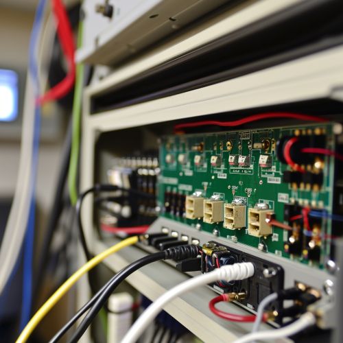
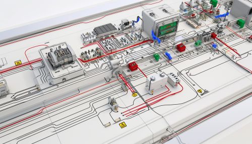
A schematic, or schematic diagram, is a representation of the elements of a system using abstract, graphic symbols rather than realistic pictures. A schematic usually omits all details that are not relevant to the key information the schematic is intended to convey, and may include oversimplified elements in order to make this essential meaning easier to grasp.


History
The use of schematic diagrams can be traced back to the earliest forms of symbolic communication. Ancient cultures used symbolic drawings to record and convey information, a practice that has evolved over time into the creation of modern schematic diagrams.
Types of Schematics
There are several types of schematics, each designed to convey specific types of information. These include electrical and electronic schematics, hydraulic and pneumatic schematics, and piping and instrumentation diagrams (P&IDs).
Electrical and Electronic Schematics
Electrical and electronic schematics are the most common types of schematics. They are used to represent the elements and connections in an electrical or electronic circuit. These schematics use standardized symbols to represent different components, such as resistors, capacitors, diodes, and transistors.
Hydraulic and Pneumatic Schematics
Hydraulic and pneumatic schematics are used to represent the elements and connections in a hydraulic or pneumatic system. These schematics use standardized symbols to represent different components, such as pumps, valves, cylinders, and accumulators.
Piping and Instrumentation Diagrams
Piping and instrumentation diagrams (P&IDs) are a type of schematic used in process engineering. They show the interconnection of process equipment and the instrumentation used to control the process. The symbols used in P&IDs are generally standardized and regulated by industry standards.
Reading Schematics
Reading a schematic requires understanding the symbols used and the rules for interpreting the arrangement of the symbols. The key to reading a schematic is to understand that every symbol and connection represents a part of the system. The arrangement of the symbols on the schematic usually does not correspond to the physical layout of the actual system.
Creating Schematics
Creating a schematic involves several steps, including determining the system to be represented, choosing the appropriate type of schematic, identifying the components and connections to be included, and drawing the schematic using standardized symbols and conventions.
Applications of Schematics
Schematics are used in a wide range of applications, from electrical and electronic engineering to hydraulic and pneumatic systems, process engineering, and more. They are essential tools for designing, building, maintaining, and troubleshooting systems.
Conclusion
Schematics are an essential tool in many fields, providing a clear and concise way to represent the components and connections in a system. By using standardized symbols and conventions, schematics allow for easy interpretation and understanding of complex systems.
